Imagine this
A receiver must notice a small message among noise. More light or power may help, but real equipment adds noise too. A calculation is not the same as a working link.
THE FIELD GUIDE / 007 · COMMUNICATION
A message needs a path, a destination and a way to notice mistakes.
A sensor reading may arrive faint, corrupted or at the wrong receiver. Explore these different failures—and what each remedy costs.
Try sending it again ↓A receiver must notice a small message among noise. More light or power may help, but real equipment adds noise too. A calculation is not the same as a working link.
The page’s light detector helps explain how a message can get lost in noise. A real communication link needs tests of its sender, path, receiver and mistakes.
This ideal calculation does not establish actual data rates or reliability in changing conditions.
Read-aloud starter; not yet tested with children. The fuller science, data, figures and sources follow below.
01 / REPEATING THE MESSAGE
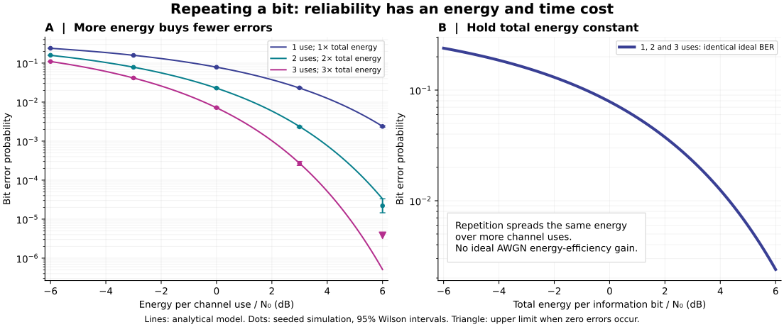
Imagine sending one bit as a positive or negative pulse. Noise nudges each received pulse. The receiver adds the noisy observations and chooses the sign of their sum. This is a simplified digital channel, not a listening test.
The reference is the energy of one baseline transmission divided by noise spectral density. Each transmission occupies the same duration.
Try this: keep three transmissions, then switch to the same total energy. The two curves overlap: the energy advantage has gone.
Solid blue: one transmission. Dashed pink: your repetition count. The vertical scale is logarithmic: each factor of ten occupies the same height. This plot varies energy along its horizontal axis; your setting is summarized above and in the table.
| Transmissions | Bit error probability | Energy | Duration | Information rate |
|---|
With independent Gaussian noise, known timing and phase, and equally likely bits, coherent binary phase-shift keying gives P(error) = Q(√(2rγ)) at fixed energy per transmission. Here r is the number of transmissions, γ = Eᵤₛₑ/N₀ and Q is the upper tail of a standard normal distribution.
Holding the total energy Eₜₒₜ = rEᵤₛₑ constant instead gives Q(√(2Eₜₒₜ/N₀)). The receiver combines analogue-valued samples before making its decision. Majority voting on already-decided bits is a different method. Fading, synchronization errors, overhead and comparisons with modern error-correcting codes are excluded.
Replaying the same stored noisy sample supplies no independent evidence: multiplying both signal and noise by r cannot change the sign. Real repeated speech has additional human and acoustic factors that this calculation does not address.
02 / THE JOURNEY OF A MESSAGE
An address says who should receive a message. It does not supply the physical path. A check can detect some changed bits; it does not prove who sent them.
What produces the signal, how does it propagate, and what receiver responds to it? State distance, power, bandwidth and delay. An unspecified transport mechanism remains unevaluated.
The receiver must distinguish alternatives despite noise. More power, less loss, lower noise or a different code may help under different constraints.
Receiver and sender need compatible framing and conventions. A correctly delivered number can still use the wrong units, destination or interpretation.
03 / ACCOUNT FOR THE SIGNAL
A link budget adds gains and subtracts losses in decibels. These controls are an abstract power accounting example with a fixed receiver measurement band; they are separate from the optical scenario below.
dBm compares power with 1 milliwatt. A gain or loss in dB is a ratio. Received power = transmitted power + gain − loss. SNR = received signal power − noise power, using matching units and bandwidth.
A 3 dB increase is approximately a doubling of power. It is not a fixed reduction in errors across every modulation scheme.
04 / A CONVENTIONAL OPTICAL EXAMPLE
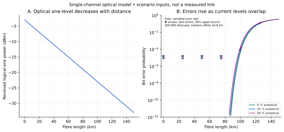
A transmitter sends two optical power levels. A photodetector converts arriving light into current. Attenuation brings the two current levels closer; electrical noise blurs the receiver’s decision.
Temperature changes only the thermal-noise term here. It does not change fibre loss or laser behaviour in this model.
The curve uses your selected temperature. Values below 10⁻¹² are clipped at the bottom of this graph, not asserted to be zero. The table retains smaller probabilities down to a display threshold of 10⁻³⁰.
| Length (km) | Received one-level power (dBm) | Bit error probability |
|---|
One intensity-modulated, direct-detection channel: illustrative band 1550 nm, 1 Gbit/s, noise bandwidth B = 0.7 GHz, transmitted logical-one power 0 dBm, dim level one tenth of the bright level, fixed loss 3 dB and attenuation 0.20 dB/km. These are scenario choices, not a cable guarantee. Wavelength is descriptive here, not a variable in the equations.
At distance d, P₁ = 10⁻³ × 10^−[(3 + 0.20d)/10] W and P₀ = P₁/10. Responsivity is 0.8 A/W; Iᵦ = 0.8Pᵦ. Gaussian current-noise variance is σᵦ² = 2q(Iᵦ + Iᵈ)B + 4kTB/R, with Iᵈ = 10 nA, R = 50 Ω, q = 1.602176634 × 10⁻¹⁹ C and k = 1.380649 × 10⁻²³ J/K. Constant dark-current offset is implicitly removed.
The threshold θ = (I₁ + I₀)/2 gives average error probability ½[Q((I₁ − θ)/σ₁) + Q((θ − I₀)/σ₀)] for equally likely bits. The variances differ, so this midpoint is not claimed to be optimal. No dispersion, nonlinearities, laser intensity noise, clock recovery, error-correcting code, multiplexing or installed hardware is modeled. Counting wavelengths alone cannot establish a usable data rate.
05 / DOES THE MESSAGE ARRIVE INTACT?
This invented teaching frame has three bytes: address, command and an eight-bit cyclic redundancy check (CRC). Toggle received bits below. The first row is the address, the second the command, the third the check.
Sent bits: address / command / check
Integrity check
Destination check
Try this: restore the frame, then change the receiver’s address. The CRC still passes, but the message is for someone else. Next try the undetected-error example: consistency of a short check is not proof that every bit is unchanged.
The CRC uses polynomial x⁸ + x² + x + 1 (0x07), initial value zero, no reflection and no final XOR. It processes address then command, most significant bit first. The received check byte is compared with a recomputed check over the received body.
The example undetected error XORs the 24-bit frame with 0x000107, changing the command and check together. It is a specific nonzero pattern the polynomial does not detect. This receiver checks and rejects; it does not correct errors. A request to resend needs a return path, while error-correcting decoding needs a specified code and decoder.
An address is not authentication. A CRC is not a cryptographic signature, and replaying an old valid frame can pass the same check. No acoustic waveform, hardware actuator, authorization policy or freshness mechanism is demonstrated.
06 / REPRODUCIBLE STUDIES
SOFTWARE EXPERIMENTS AND ANALYTICAL CURVES · NO PHYSICAL LINK TESTS
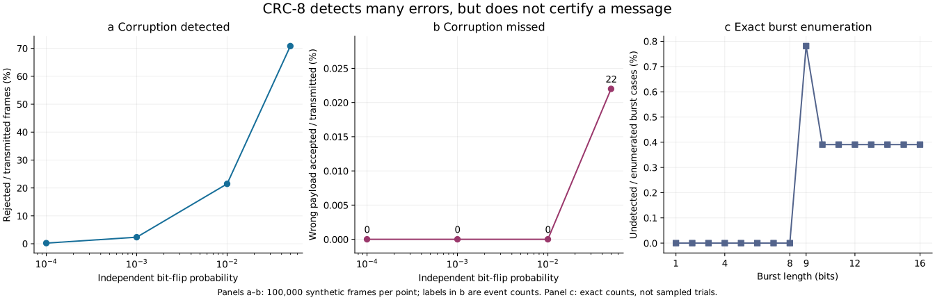
At a bit-flip probability of 0.05, the simulated CRC receiver accepts 22 corrupted payloads out of 100,000 transmitted frames; 70,846 frames were corrupted, so the conditional undetected fraction is 22/70,846. Uniformly random 24-bit candidates pass this check 383 times in 100,000 trials, consistent with a theoretical probability of 1/256 for that specific uniform model. This is not an acoustic false-trigger rate.
To reproduce the figures, run each Python script in its own folder with Python 3, NumPy and Matplotlib installed. Each writes its output beside itself. The three studies test separate models; their sample counts cannot be added into a single reliability trial.
A confidence interval describes sampling uncertainty within the chosen model. It does not account for omitted physics or establish hardware performance. Seeing no errors in 200,000 bits only gives a one-sided 95% upper bound of about 1.5 × 10⁻⁵ under independent Bernoulli trials; it cannot establish a 10⁻⁹ error rate.
07 / WHAT THIS COULD IMPROVE
Compare retransmissions with battery use and delivery time. A modeled reduction in errors is useful only within the device’s actual power and timing constraints.
A documented power budget exposes missing quantities. Measured receiver behaviour and channel properties are needed before predicting a real installation.
Ask whether bits are consistent, whether the destination matches, whether the sender is authorized and whether the message is current. These questions need different evidence.
08 / FROM MODEL TO MEASUREMENT
For an ordinary test link, record the transmitted and received bit sequences, total bits, error count, rate, power settings, distance and measurement bandwidth. Keep corrupt and missing frames as separate outcomes.
Compare one change at a time under both fixed-per-use and fixed-total-energy conditions. Repeat across relevant conditions and report how noise or loss was measured. Retain raw counts and intervals, including zero-error cases.
This is a proposed evaluation outline. The studies above execute numerical models only; they do not certify a device, recover a new transport mechanism or establish production reliability.
READ FURTHER
MIT OpenCourseWare · Communication systems, Chapter 4 explains physical channels, modulation, noise and receiver decisions; sections 4.1–4.2 provide context for the diagram and Gaussian decision models.
NIST · Cyclic redundancy check explains accidental-change detection and its distinction from cryptographic protection.
RFC 3385 · CRC and checksum considerations discusses how undetected errors depend on polynomial, message length and error model. It does not endorse this teaching frame for a real system.
ITU-T G.652 · Single-mode optical fibre and cable provides standards context. The attenuation and receiver values used here are explicitly illustrative, not specifications inferred from this standard.
Revised 27 September 2026. All figures are original numerical teaching studies with downloadable methods.
Choosing a high acoustic frequency does not automatically make a command inaudible. A nominal 15 kHz signal is not guaranteed to be inaudible to every listener; audibility depends on the listener, sound level and signal characteristics. Buss and colleagues measured detection at 16 kHz, showing that high-frequency sensitivity and the test signal both matter. A command link still needs a defined transmitter, receiver, code and measured detection performance. Colour or shape can label a destination; neither confirms that its actuator received the command.
To assess a proposed interference problem, specify what varies with time, the transmitter and receiver, the signal frequency and the errors actually observed. A magnetic-field value at one location does not by itself establish that every electromagnetic link fails. Proposing a different carrier still requires a demonstrated transmitter, receiver and measurable transfer of information.
A REAL EXPERIMENT · 2012
Neutrinos interact weakly with matter: that helps them pass through it, but makes them hard to detect. Researchers at Fermilab demonstrated a message link using the NuMI beam and MINERvA detector.
This was a low-rate experiment using large research infrastructure. The authors emphasized the improvements needed for practical use. The result demonstrates a specified link; it does not establish a portable communicator or validate another proposal that merely names the same carrier. Stancil and colleagues: primary experiment and methods (2012).
What could it help with? The research question is whether messages can cross barriers that block ordinary radio. A useful system would also need an achievable transmitter, reliable receiver, sufficient data rate and an acceptable energy cost. Those requirements remain separate from proving that a message can be decoded. See the unspecified proposal and its missing evidence.