Imagine this
A camera can see bright dots in the sky. If we know which dots are which stars, their pattern can show the camera's direction. Knowing the pattern is different from teaching a camera to recognize it.
THE FIELD GUIDE / 024 · STAR NAVIGATION
Star trackers connect light on a sensor to orientation in space. Recognising the stars, measuring their directions and trusting the result are separate tasks.
A camera can see bright dots in the sky. If we know which dots are which stars, their pattern can show the camera's direction. Knowing the pattern is different from teaching a camera to recognize it.
Star-angle geometry and camera calibration explain celestial direction measurements. A navigation instrument would need recognition, calibration and real-sky testing.
The calculation assumes known star matches; it does not demonstrate automatic recognition or an operating instrument.
Read-aloud starter; not yet tested with children. The fuller science, data, figures and sources follow below.
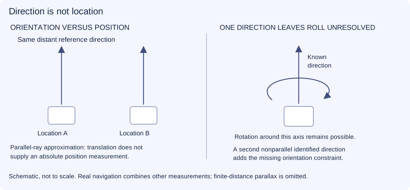
A camera looking at the sky can compare the pattern it sees with a catalogue. When enough stars are reliably matched, their directions help reveal which way the camera points. This is orientation. It does not, on its own, tell the camera its absolute position in space.
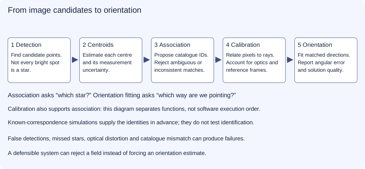
A star tracker first finds candidate points in an image and estimates their centres. It then tries to associate those points with catalogue entries. Finally, camera calibration converts image positions into directions that can be used to estimate orientation. Dust, sensor artifacts, blur or a missed star can interfere at different stages. NASA star-tracker engineering report
A single identified direction still leaves the camera free to rotate around that direction. Several suitably separated stars provide more geometric information. Recognising a pattern and measuring a precise angle are different achievements.
SYNTHETIC DIRECTIONS
Six invented directions are projected through a pinhole camera with focal length 800 pixels. Their labels are known in advance. This demonstration rotates the camera-coordinate directions about the optical axis; it does not search a star catalogue.
Angle between directions 1 and 2: . Dot size is a drawing choice, not a stellar diameter or measured brightness.
The plot uses image-plane coordinates centred for display and draws positive vertical direction upward. The invariance is a geometric fact, not evidence that a real matching algorithm will recognise a noisy or partly hidden pattern.
The lens, focal length and distortion determine how directions appear on the sensor. A pixel displacement cannot become an angular measurement without that relationship. Star colour and detector response can also affect measurement. Real calibration facilities test these effects rather than treating an attractive star image as sufficient evidence. ESA calibration example
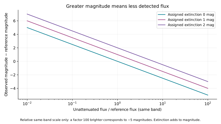
Astronomical magnitude is a logarithmic brightness convention. In the same measurement band, an object 100 times brighter has a magnitude 5 units lower. The scale compresses large brightness differences into manageable numbers; its reversed direction is a convention, not a reversal of energy.
The measurement band and reference matter. A value in one filter cannot simply be compared with a value in another as if both measured exactly the same light. Spitzer instrument photometry handbook
Apparent brightness is what reaches us. It depends on the object, distance and intervening absorption. More dust along a line of sight can reduce the arriving flux and increase the magnitude number. Brightness alone does not uniquely determine distance or intrinsic luminosity.
SAME-BAND BRIGHTNESS
Use a positive flux ratio measured relative to a reference in the same photometric band and convention. The reference has a magnitude difference of zero. Extinction means dimming along the line of sight.
Try 100, 1 and 0.01 with zero extinction: the differences are −5, 0 and +5 magnitudes. Zero flux has no ordinary logarithmic magnitude. In a real observation, a non-detection may support a sensitivity-dependent limit rather than a precise magnitude.
One magnitude of extinction adds one to the magnitude difference and multiplies flux by about 0.398. These calculations do not infer an object's distance or intrinsic luminosity.
A method that succeeds on every example in a small test has succeeded on those examples. That does not establish that errors are impossible. A meaningful report states what was tested, which cases were rejected, which were wrongly matched and how the reference was obtained.
Finding candidates is also not the same as identifying stars. A detector can recover many real points while adding many false ones. An orientation solver needs reliable associations, and should sometimes say that the evidence is insufficient. ESA star-tracker challenge
Star-based orientation supports spacecraft pointing and astronomical observation. Brightness measurements help compare observations taken with a declared instrument and calibration. Better calibration and rejection of misleading points could make these systems more dependable, but improvements need independent test data and reference measurements.
Our synthetic geometry and brightness demonstrations explain selected relationships. They are not a flight-qualified navigation system, a new star catalogue or proof of an exceptionally low error rate.
REPRODUCIBLE STUDY
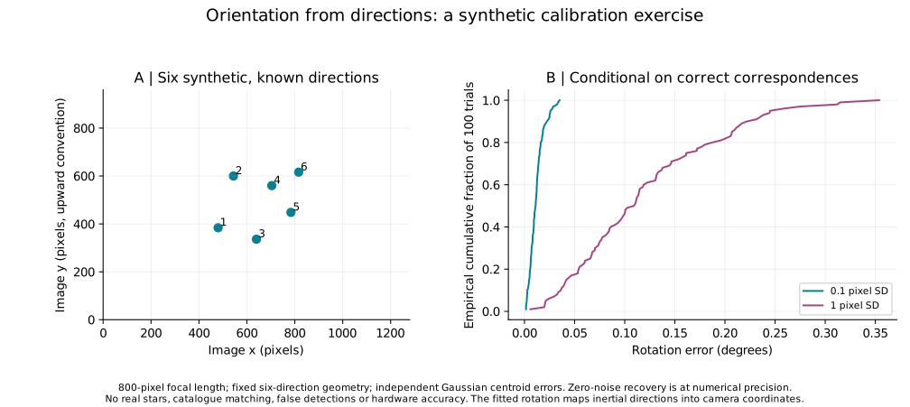
The downloadable study contains six reference directions, 300 seeded orientation trials, three noise-level summaries and 303 brightness cases. Jointly reordering known pairs preserves the estimate; reassigning their identities is a different, incorrect correspondence problem.
The numerical orientation study supplies the correct association between six synthetic reference directions and six image points. It applies a known inertial-to-camera rotation, adds specified centroid noise and fits a rotation using singular value decomposition. It therefore tests orientation estimation after association, not how stars are identified.
A single direction cannot determine a full three-dimensional orientation: rotation about it remains free. Wrong associations, optical distortion, moving stars, detector artifacts, missing stars and real catalogue errors require separate tests. A real tracker should reject an ambiguous solution rather than silently returning a confident direction.
For positive same-band flux ratio q, Δm = −2.5 log₁₀(q), with inverse q = 10^(−0.4Δm). Extinction A gives qobs = q·10^(−0.4A). For micro-Vega flux in the WASP bandpass, the NASA Exoplanet Archive documents m = 15.0 − 2.5 log₁₀(F); subtracting two magnitudes in that same band cancels the 15.0 zero point and gives the relative formula above. Reference flux and magnitude zero points differ between photometric systems; this relation does not assume one universal zero point.
Our figures use synthetic geometry and assigned measurement errors. They are not a new star catalogue, a flight qualification, or a proof that an exceptionally small failure probability has been achieved.