Imagine this
Sunlight can warm things. A solar panel can turn some light into electricity. A bright spot does not tell us how much useful energy we caught.
THE FIELD GUIDE / 018 · LIGHT AND HEAT
A photon has an energy. A beam has a power. A surface can absorb, reflect and emit radiation. Keeping these quantities separate helps explain lighting, temperature measurement and solar heating.
Sunlight can warm things. A solar panel can turn some light into electricity. A bright spot does not tell us how much useful energy we caught.
Today, photon and heat calculations help compare light sources, detectors and sunlight collectors. A collector for a particular task would need measured losses and output.
The page's 1,820 cases are calculations, not a built solar device; area, spectrum, conversion losses and sustained input matter.
Read-aloud starter; not yet tested with children. The fuller science, data, figures and sources follow below.
At a fixed optical power of one watt, a monochromatic beam transfers one joule every second. Changing its wavelength changes the energy of each photon, so the photon rate changes too. A 500 nm photon carries about 2.48 electronvolts; longer-wavelength photons carry less energy each.
This does not tell us whether the beam cuts a material. That also depends on absorption, delivered energy, area, time and material response. The photon experiment is an energy ledger, not a cutting-performance calculation or equipment guide.
An electrically driven light-emitting device takes energy from a supply. Its material and structure determine how electrical excitation becomes an emitted spectrum and losses. Its wavelength alone does not tell us electrical efficiency, brightness, colour reproduction or lifetime.
Electrical input supplies both optical output and dissipative losses; no efficiency is assigned to the unspecified material. Electroluminescence and thermal emission are different mechanisms; the following warm-surface calculation does not model an unspecified light-emitting material.
Two surfaces at the same temperature can emit different amounts in a given spectral band. Emissivity describes that difference relative to a blackbody reference. A detector may also receive light reflected from the surroundings.
Our comparison assigns a 330 K surface,293 K black isotropic surroundings and an opaque diffuse gray surface. The experiment below separates emitted radiance, reflected-background radiance and their sum at the chosen infrared wavelength. Lower emissivity reduces the emitted part while increasing the reflected part under these assumptions.
If the surface and its surroundings share the same temperature, the two contributions sum to the blackbody radiance regardless of emissivity in this model. That limiting example shows why a bright detector reading is not automatically evidence of a hotter surface.
The units are watts per square metre per steradian per micrometre: power resolved by direction and wavelength. This is not total radiated power or a camera temperature. Instrument response, atmosphere and real reflection geometry are omitted. Thermal-camera colours are a display convention, not visible glowing colours. A matte appearance alone does not supply an infrared emissivity.
Mirrors can send sunlight from a collecting aperture toward a smaller receiver. They do not create additional energy. The projected optical aperture is distinct from the receiver's hot emitting area and from the land occupied by an installation.
The hypothetical solar ledger declares irradiation, optical throughput and solar absorptivity, then subtracts prescribed radiative and convective losses from absorbed input at a chosen receiver temperature. The temperature is an input to this illustration, not a solved equilibrium.
A negative remainder is meaningful: under these assumptions the solar input cannot sustain that temperature without extra heat, even before any useful heat is extracted. The displayed negative sign identifies this deficit; it is not a working operating point without additional input.
Solar absorptivity and thermal-infrared emissivity cover different wavelength ranges and need not be equal. The familiar absorption–emission relation applies to matched spectral and directional conditions; it does not equate unrelated broadband averages.
For lighting, compare optical output with electrical input rather than judging efficiency from wavelength. For noncontact temperature sensing, identify reflected surroundings and emissivity assumptions. For solar process heat, keep collection area, receiver losses and useful extraction in one declared balance.
These are tools for examining a proposal. No particular emitter, receiver, cutting device, annual yield or power plant is validated here.
EXPERIMENT 1 / FIXED OPTICAL POWER
E=hc/λ; photon rate=P/E. Exact SI constants are supplied in the downloadable method. One watt remains one joule per second. This calculates no absorption or cutting threshold.
EXPERIMENT 2 / EMITTED PLUS REFLECTED
Surface 330 K; black isotropic surroundings 293 K. All displayed radiances: W m⁻² sr⁻¹ µm⁻¹.
Lseen=εBλ(T)+(1−ε)Bλ(Tenv), using Planck spectral radiance. Opaque diffuse gray surface, view filled, unit transmission. No atmosphere, real reflection geometry or instrument spectral response. These numbers are not camera temperatures or hemispheric power.
EXPERIMENT 3 / KEEP THE DEFICIT VISIBLE
Direct irradiance 800 W/m²; optical throughput 0.7; solar absorptivity 0.9. Separate receiver area 0.2 m², infrared emissivity 0.8, convection coefficient 5 W/(m² K); surroundings 293 K.
Pabsorbed=I Aaperture ηoptical αsolar. Radiation=εIR σ Areceiver(T⁴−Tenv⁴); convection=h Areceiver(T−Tenv). Remaining heat=input−both losses. Kelvin is used in fourth powers. Radiation assumes a large isothermal surrounding enclosure with view factor one. No equilibrium solution, annual yield, land-area conversion, electrical cycle or real device prediction is supplied.
ORIGINAL ANALYTICAL FIGURES
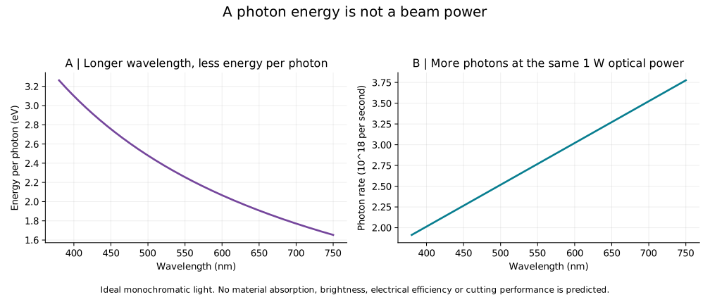
Full-size photon figure · Photon CSV
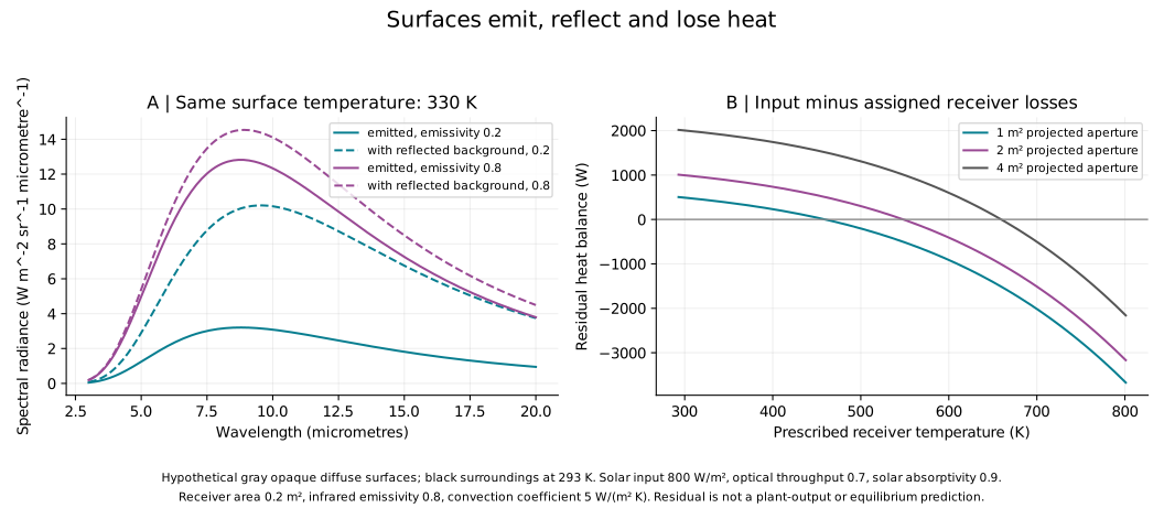
Full-size thermal figure · Radiance CSV · Solar CSV · Methods · Reproduce studies · Parameters and checks
Independent checks test photon energy accounting, equal-temperature reflection/emission, all-row solar conservation, the blackbody peak and integration of Planck radiance against total blackbody emission. These check implementation, not physical-device validation.
The material-specific paper demonstrates an independent research example; its mechanism and performance are not transferred to an unspecified material. All collector and surface coefficients here are hypothetical.
Back to the field guide →The land occupied by a solar installation is not the same as the collector area intercepting sunlight. Converting that light to useful heat and converting heat to mechanical work are also different stages. An efficiency needs a stated input, output and operating conditions. A large site area and a percentage alone do not tell us how much mechanical power the installation delivers.
A glowing surface and a display solve different problems. To draw a symbol, separate regions must be controlled independently: one region might brighten while its neighbour stays dark. A proposal to control these regions through local electric charge therefore also needs a measured relation between charge and light output, a smallest controllable feature and a response time. A list of emission wavelengths alone does not establish the range of colours a display can reproduce. No usable display resolution, refresh rate or brightness is demonstrated for the proposed material here.