Discharge channel
The ring-shaped region where incoming propellant is ionized and accelerated. The cutaway lets you see inside.
DMGB SYSTEMS / AN EXPLANATORY CAD MODEL
Electricity helps send propellant backwards. The spacecraft gets a push forwards.
Imagine letting go of a balloon: air goes one way and the balloon goes the other. A space engine also pushes matter out. This kind uses electricity to help speed up tiny particles. It still needs both propellant and power.
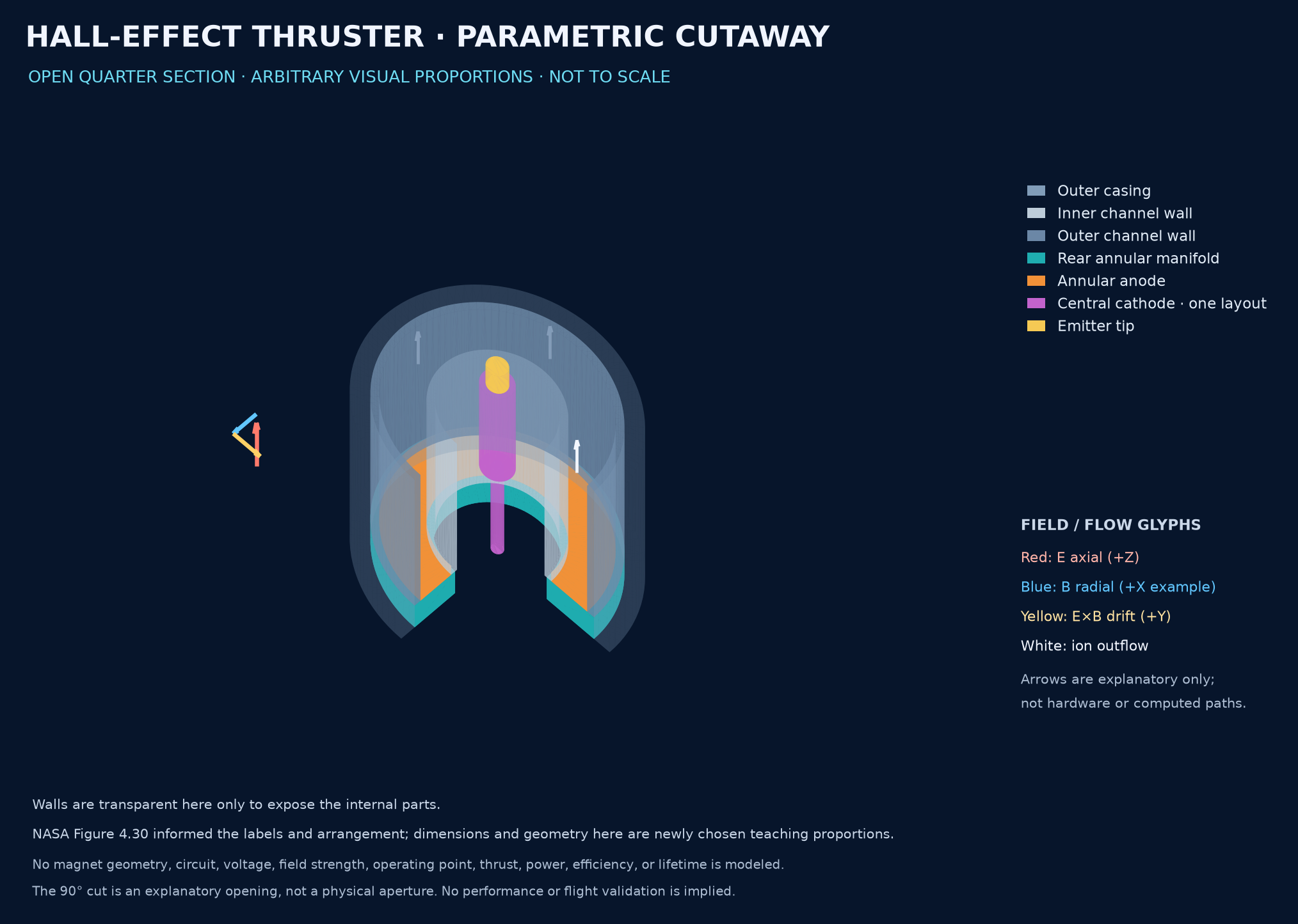
The ring-shaped region where incoming propellant is ionized and accelerated. The cutaway lets you see inside.
The electrode at the rear of the channel. In this explanation it also represents where incoming propellant is distributed.
Supplies electrons to the discharge and the outgoing plume. Other Hall thrusters place this component outside the main body.
Crossed electric and magnetic fields affect how electrons move near the channel exit. Electron collisions help ionize propellant atoms. The electric field accelerates the positive ions mainly out along the axis. In this account, the ions are comparatively weakly affected by the magnetic field.
The cathode also supplies electrons to the outgoing plume, keeping it approximately charge-neutral. Electron drift around the annulus and conventional current must not be treated as the same direction. This model does not calculate either.
There is no acceleration grid in this schematic: gridded-ion thrusters use a different architecture. Magnet hardware, electrical circuits, feed details and thermal design are omitted. No field map, operating point, thrust, efficiency or lifetime is predicted.
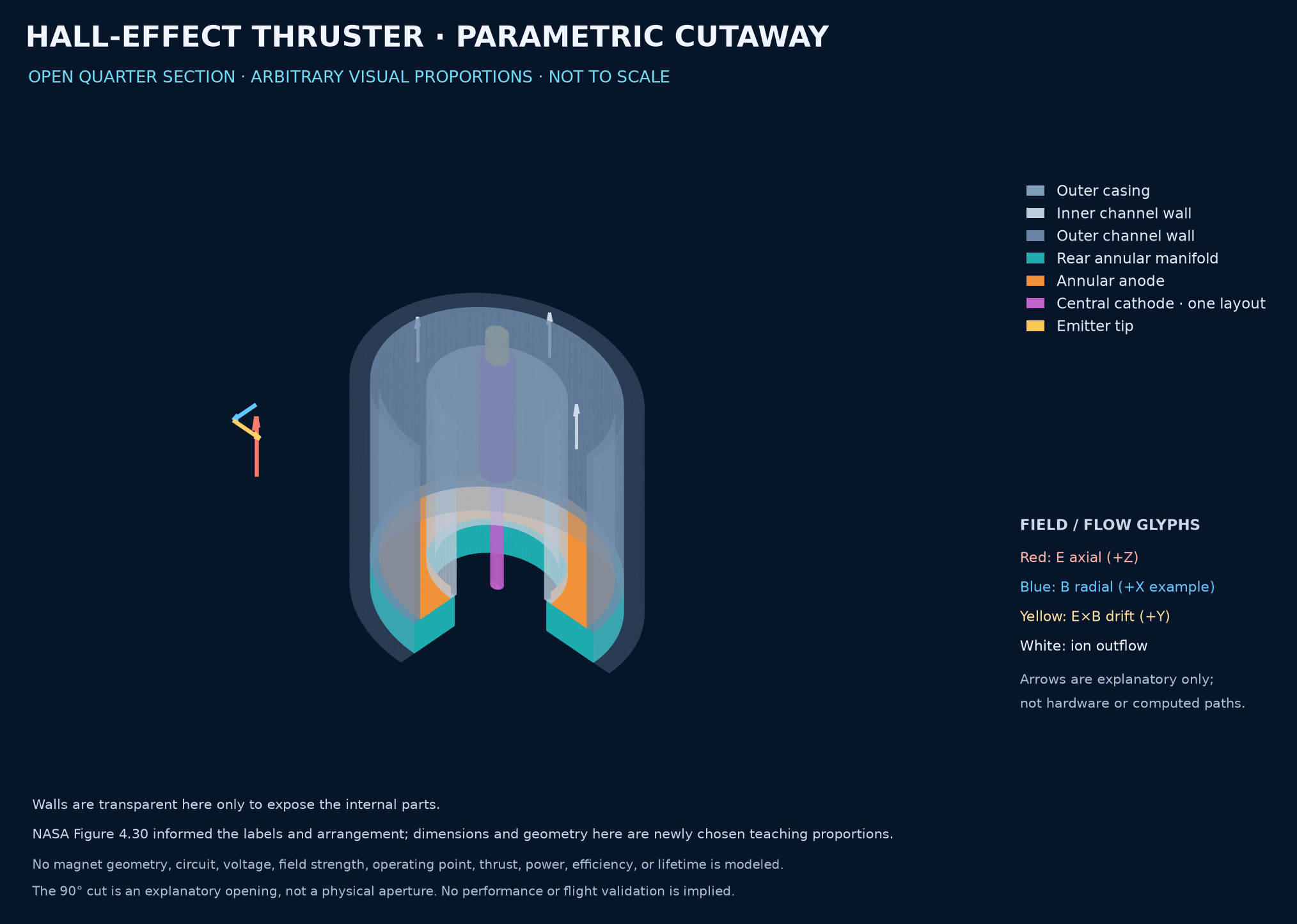
Electric propulsion can help spacecraft change or maintain their orbits while using propellant efficiently. Those spacecraft can support communications, observation and exploration. Whether a particular engine is useful depends on its power needs, thrust, lifetime and mission requirements; this drawing cannot answer those questions.
The source script builds the geometry; STEP preserves solid geometry and STL provides a triangular mesh. The files are educational models, not fabrication instructions.